Get a blue kkl usb cable from ebay. They can be modified. This guide is written to show the easiest way to do the modification so you can have a cheap OBDII interface cable of your own, which will sense the Ignition On in INPA.
PREREQUISITES
You need to have a fine tipped soldering iron and the skills to use it. The work that needs to be done is very fine and requires mm precision.
STEP 1
Get a usb kkl cable off ebay. You can have them sent from China for a really cheap deal but from the UK these can still be found for less than ten squid.
STEP 2
You’re going to need to get down to Maplins and buy some bits (or just rummage through your boxes for the bits). What you need
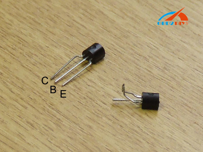
1x NPN transistor (2n3904)
1x resistor 220k (can vary down to 100k or up to 400k)
you also need a bit of solder and a little bit of wire
STEP 3
Open up the cable by removing the four philips/pozidriv screws (two per side). Remove the casing
STEP 4
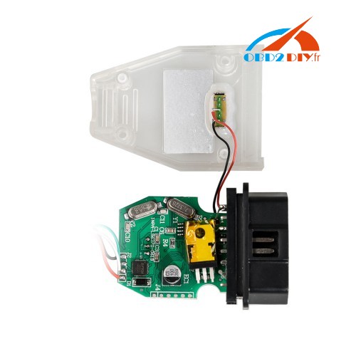
cut the bit of wire to length and solder it to the back of pins 7 + 8 – you can also just use solder to bridge the pins
STEP 5
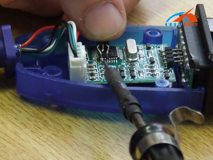
Use solder to bridge pins 17 and 18 of the fdtl chip – this will form a base for the next step which is tricky otherwise.
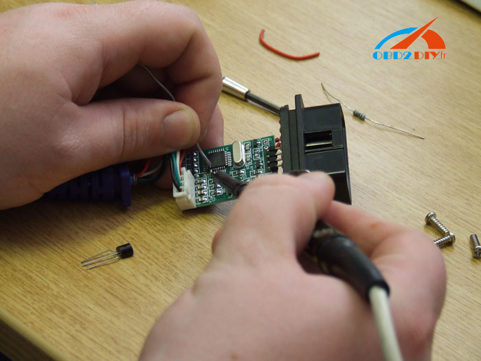
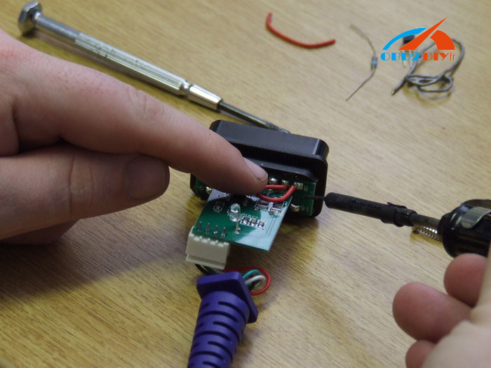
Then take the transistor, cut the legs so they are about 1cm long and bend the outer two down and together so there is about a 2mm gap between them. Use the iron to dab a bit of solder on to each of the three legs – note the labelling
STEP 6
Solder leg (E) to the bridged pins 17 and 18. If you’ve prepped well this will be simply a case of holding the transister against the top of the fdtl chip, lining up the leg and dabbing it with the iron. Check if the C leg is sitting over pin 20 (there should be a pin that you avoid between the two that were bridged). If it isn’t, bend it so it sits over it and then dab it with the iron. The solder that you put on the leg before should be enough to get them to join. Keep going until they are stuck together.
STEP 7
Now take the resistor and cut one leg short (about 1.5cm). Then solder this leg to the middle ‘B’ pin of the transistor (the only one now not connected)
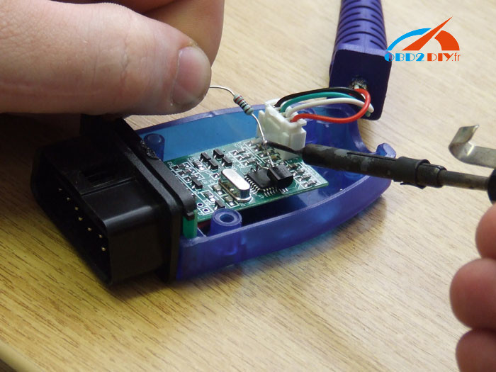
Then bend the resistor so the other leg sits against the back of pin 1. and solder that on too.

STEP 8
Put the case back on. Job done. You should now have a working USB-OBDII cable that has ignition detection and works in INPA, DIS, and SSS.
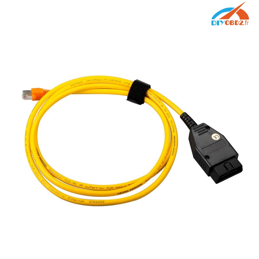
Note: it’s your own risk. if you are not experienced, you’re advised to a decent INPA cable:
http://www.obd2diy.fr/wholesale/bmw-inpa-kcan-with-ft232rq-chip-with-switch.html


This K+Dcan cable comes with a switch pin 7 & 8 and FT232RQ chip
on DCAN cars one pin is used for a ethernet connection and the other to the K data line – on K line cars, both pins are connected to K data lines and that creating a switch mode circuit would cost more than the interface is worth. The 2 most sensible options are both hardware-related:-
- Use an adapter (such as the one sold by One Stop electronics) which internally bridges pins 7 & 8 or…
- Mount a small switch on the OBD plug end of your adapter, which can bridge (for K line) or separate (for DCAN) the connection between pins 7 & 8.