What tool to use:
BMW ICOM cable for E/F/G/I-series
Tip: ICOM Next vs ICOM A3 vs ICOM A2 vs ICOM A
Which software to work together:
INPA for E-series
E sys for F-series
ISTA-P for all BMW cars
Newest: 2017.12 ISTA-D 4.08.12 ISTA-P 3.63.0.400
Cheapest: 2015.10 ISTA-D 3.51.30 ISTA-P 3.56.5.002
Note: both tested 100%, use with relief
How to start the ISTA workshop system:
- Double click theISTAicon in the Windows desktop created during the installation process above.
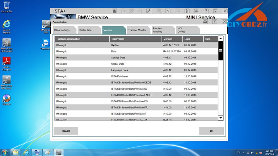
After ISTA is started, the start screen appears. A list of news is displayed. You can set the display period in the Administration.
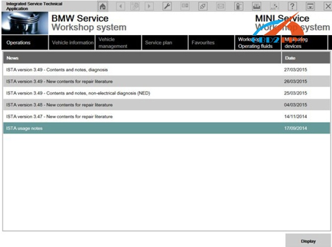
Once you have read the “Note on using ISTA”, close the dialog using the button “Next”. You can open a process from the start screen: Select the “Operations” menu.
Select a vehicle without a cable connected to car
Method 1:
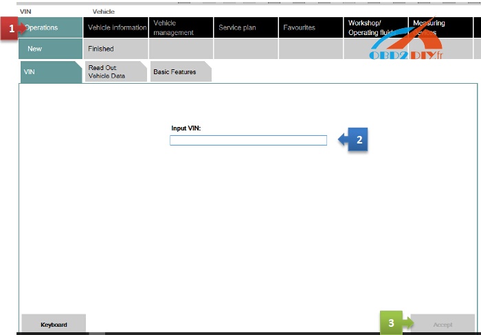
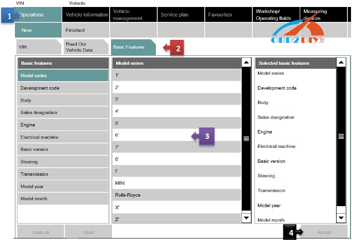
You can enter your short VIN (Last 7 of the VIN) and be able to pull relevant procedures or troubleshooting instructions without actually connecting to the car. To access this feature, launch ISTA+ and click on Operations tab (1). Then enter the short VIN into the VIN box (2). Then click on Accept (3). The Accept button will become active only when a VIN number is entered. You can explore features specific to your car from here.
Method 2:
Follow the steps as in the picture below:
Select a vehicle via “READ OUT VEHICLE DATA” with cable connection to car
After you select the “Operations” menu from the start screen, the workshop system changes to the “Vehicle identification number” tab under the “New” menu item.
We will assume that you have connected the right interface to the car at this time (Refer to interfaces section). Our example will use ICOM.
This is how to identify a vehicle by reading out the vehicle data, while automatically creating a process:
- Click the “Operations” main menu item in the navigation area.
- Select the “Read out vehicle data” tab and follow the instructions provided.
- Click the “Identification without vehicle test” or “Complete identification” button.
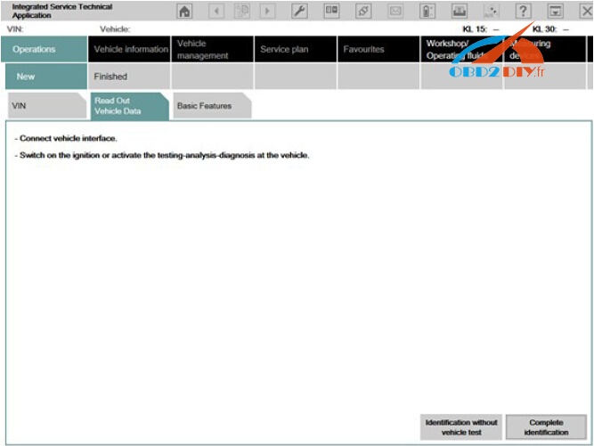
The connection to the vehicle is now established. The workshop system performs an identification of the vehicle. It also reads the vehicle identification number and further data from the vehicle. The progress of the identification operation is displayed on a progress bar.
If an ICOM has the status “Firmware” and cannot be selected, then you have to carry out an ICOM firmware update first.
Again, ICOM troubleshooting is not discussed here, there are forum threads dedicated to troubleshooting communication issues. Refer to those.
Start vehicle test
If vehicle identification was called up via “Read out vehicle data” and “Complete identification”, the vehicle test starts automatically following vehicle identification, followed by the vehicle operation and service data transfer and analysis. The control unit tree is displayed during the vehicle test
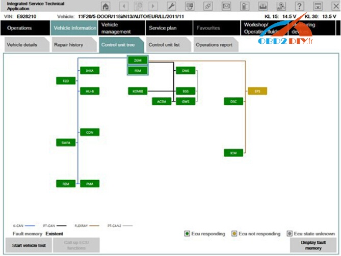
Here you can observe the ongoing determination of the control units that are fitted. If no control unit tree is available, the “Control unit list” mask is displayed automatically.
The control unit tree contains all the control units identified in the vehicle and displays their allocation to the relevant bus system. The control units are identified in succession and their fault memories are read out. The color then changes to display of the detected state. An explanation of the colors can be found in the lower section of the displayed mask. From this screen, if required you can restart the vehicle test or also call up control unit functions so that you can read out measurements or activate actuating elements.
Before you can access a test plan you must first display the fault memory. This is how to view the fault memory:
- Wait until the vehicle test is completed.
- Click the “Display fault memory” button.
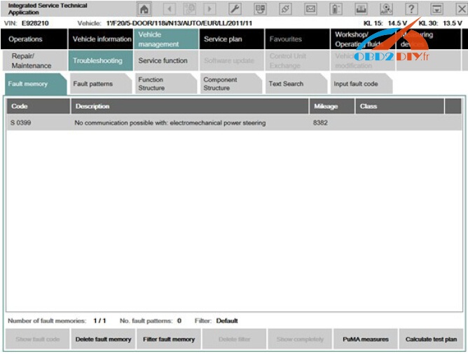
Show fault memory
After the vehicle test, click the “Display fault memory” button in the “Fault memory” mask. The fault codes that are read out and the associated description are listed here.
The function “Delete fault memory” can be carried out at the end of the guided troubleshooting. In order to start the guided troubleshooting, first calculate a test plan.
This is how to calculate a test plan:
- Click the “Calculate test plan” button.
Processing the test plan
The test plan lists the components and functions that might have caused the fault. The documents and test modules corresponding to the components and functions are displayed in the “Type” column, identified with “ABL”. In the “Type” column, documents and test modules are identified with an abbreviation.
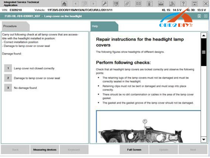
Procedures localize a fault and give advice on rectifying it. This is how you start a procedure:
- Select the required procedure from the test plan.
- Click the “Display” button.

The priority in the test plan does not necessarily specify the call-up of the processes. The priority is to be regarded as a recommendation for processing.
A test module is primarily designed to identify the cause of a fault. Furthermore, service functions can be performed via procedures. Information can be displayed within a test module, as well as measured values read out or entered. Furthermore, queries can be made available in procedures via selection screens.
After a test module has been carried out, additional information is added to the test plan if this is necessary for further troubleshooting or fault elimination.
After the test plan has been completed, you should carry out the “Delete fault memory” function.
Information types in ISTA documents – what do things mean?
| Abbreviation | Information type | Abbreviation | Information type |
| ABL | Procedure (service program) | REP | Repair instructions |
| AZD | Tightening torque | SBS | Operating fluids |
| EBO | Installation location | SIT | Service Information Engineering |
| FEB | Fault elimination | SPI | Vehicle software information |
| FTD | Vehicle engineering diagnosis | SSP | Wiring diagram | |
| FUB | Functional description | STA | Connector view details | |
| IBAC | Internet Based Calculation of Enabling Codes | SWS | Special tool / device | |
| KFA | Function changes to vehicle | Special tools | Special tool | |
| MSM | BMW Group Mobile Service | TED | Technical data | |
| PIB | Pin assignments | |||