This is detailed guide on how to setup CM TECH 2.
Requirement for GM Tech 2 Flash Setup:
1. The GM SPS application installed onto your PC (with the USB security key).
2. 32 MB PCMCIA card recommended.
3. SPS Kit Components:
• RS-232 DB9 Serial Port Adapter (P/N 3000111)
• RS-232 Communications Cable (P/N 3000110)
• USB Security Key (already installed during software installation)
• RS-232 Loop-back Adapter (P/N 3000112)
• User’s Guide (P/N 526933)
4. Tech2 Kit Components (from Tech 2 Flash Kit):
• Tech 2 Flash Scan Tool
• Cigarette Lighter Power Cable (P/N 3000096) or Battery Power Cable (P/N 3000097)
• SAE 16/19 Pin Adapter (if the vehicle is OBD II compliant)
• NAO 12/19 Pin Adapter (if the vehicle is not OBD II compliant)
• (Optional) AC to DC Power Supply (P/N 3000113)
• DLC Cable (P/N 3000095)
• DLC Loop-back Adapter (P/N 3000110)
Step 1: Verify the Tech 2 and DLC Cable (Power On Self Test – POST)
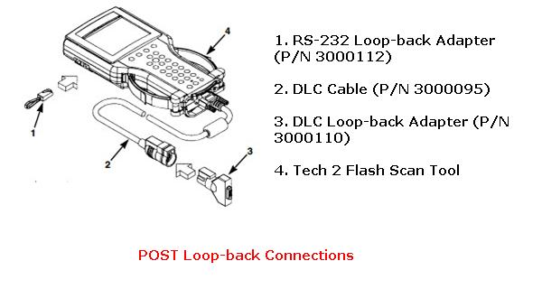
1. Make the loop-back connections as follows:
(a) Plug the RS-232 loop-back adapter (item 1) into the Tech 2 Flash RS-232 port. See Figure 2.1.
(b) Connect the DLC cable (item 2) to the Tech 2 Flash VCI connector.
(C) Connect the DLC loop-back adapter (item 3) to the DLC cable.
2. To make the power connection, connect one of the following to the power jack on the DLC cable (see Figure “POST Loop-back Connections”):
• battery power cable (item 1), or
• cigarette lighter power cable (item 2), or
• the optional AC to DC power supply

3. Supply power to the Tech 2 Flash.
4. Perform the Power On Self Test (POST) as detailed in the Tech 2 Flash User’s Guide.
5. The POST automatically verifies the hardware and detects any Tech 2 Flash malfunctions. Do one of the following:
• If any errors are detected, refer to the POST Troubleshooting Chart located in the Tech 2 Flash User’s Guide.
• If no errors are detected, go to the next step.
6. Disconnect the RS-232 loop-back adapter, the power supply, and the DLC loop-back adapter.
7. Go to the steps in the next section, “Step 2: Connect the Tech 2 Flash Scan Tool to the PC and to the Vehicle DLC”.
Step 2: Connect the Tech 2 Flash Scan Tool to the PC and to the Vehicle DLC To connect the scan tool to the PC and the vehicle
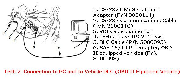
Note: USB security key installed during software installation is not shown. (Can be in USB port on front or back of computer.)
1. Connect the RS-232 DB9 serial port adapter
(Item 1) to the open COM port on your PC that you selected when you installed the SPS application.
2. Connect the RS-232 communications cable (Item 2) to the DB9 serial port adapter (Item 1) and to the Tech 2 RS-232 port (Item 4).
3. If the vehicle is OBD II equipped (Figure “Tech 2 Connection to PC and to Vehicle DLC (OBD II Equipped Vehicle)”), connect the SAE 16/19 pin adapter (Item 6) to the DLC cable (Item 5). (If the vehicle is non-OBD II equipped, skip this step.)
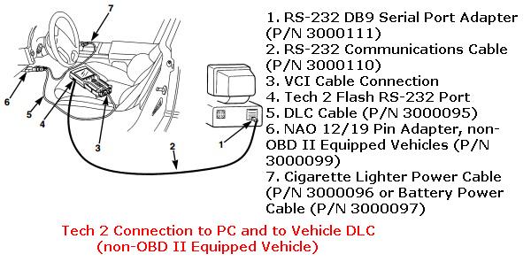
Note: USB security key installed during software installation is not shown. (Can be in USB port on front or back of computer.)
4. If the vehicle is non-OBD II equipped (Figure “Tech 2 Connection to PC and to Vehicle DLC (non-OBD II Equipped Vehicle)”), make the following connections. (If the vehicle is OBD II equipped, skip this step.)
(a) Connect the NAO 12/19 pin adapter (Item 6) to the DLC cable (Item 5).
(b) Connect a power supply (Item 7) to the DLC cable (Item 5).
(c) Connect the power supply to the appropriate power source (cigarette lighter, battery, or outlet). 5 Connect the DLC cable (Item 5) to the Tech 2 VCI cable connection (Item 3).